|
|
| Home-->F1 Rocket Project-->Elevators Page 2 |
|
SITE CONTENTS
Please send your comments and suggestions to: Copyright
© 2008 by
|
Links
on this page: Attach Right Elevator Skin Left Elevator Trim Motor Mount |
|
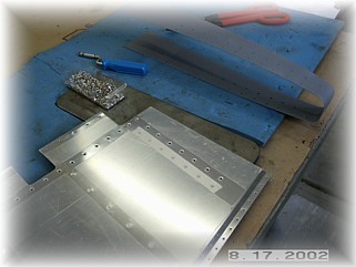
| Attach Right Elevator Skin
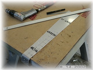
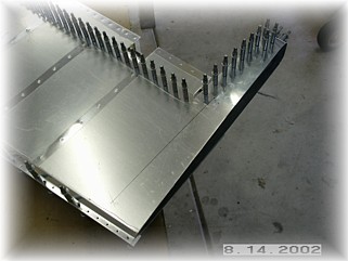
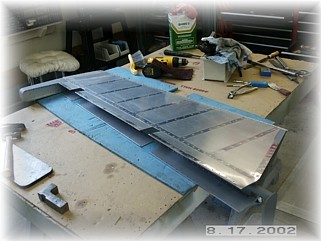
The first skin to attach to the skeleton is the tip/counterweight skin. I laid the rivet pattern out on the part over on the table and pre-drilled the holes in the skin first. This acts as a guide while I'm holding the skin on the part. Get your clamps out and drill the skin and the skeleton together. DO NOT drill any holes equal to or aft of the spar flange. These will be drilled in conjunction with the skin.
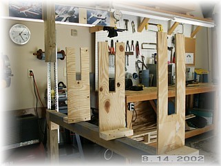
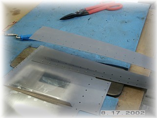
I built the jig and attached it to my crossbeam. You really don't need to make two end jigs. I just made jig #4. When it comes time to jig the left elevator with the trim tab spar, I will just screw a cross member to the #4 jig at the appropriate part. This way, I can set up and true the jigs just once and use them for both elevators. I clamped the skeleton to the two skins and drilled all the holes, starting in the center of the spar and working my way out to each end. Once that was done on both sides, I removed the elevator from the jig and brought it over to the table.
I think it is easier to drill the tip/counterweight skin to the skins over on the table. I extended the centerlines of the two rivet lines down the skin and laid out the rivet pattern. Be careful to square up the tip rib to the spar before drilling these holes. Once the tip is square to the spar, drill the two rows of holes down to the end of the tip rib.
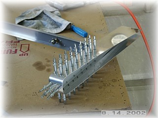
I disassembled all the part and began the tedious job of cleaning up the holes and dimpling everything. Shown above is the pop rivet dimpler that I used to get to the holes in the ends of the ribs. I can't get my squeezer in there so this little gadget comes in handy. After I dimple it, I run the countersink bit in the hole a couple of turns to true up the dimple since the pop rivet dimpler doesn't quite make as crisp a dimple as the squeezer.
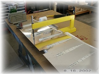
The skins are dimpled on the table using the C-frame tool.
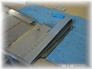
The first step in riveting the skins to the skeleton is to rivet the tip/counterweight skin to both elevator skins. This is done on the bench using your back rivet plate. Again, use easy pressure when using the back rivet plate because it is easy to overset these rivets. Remember to just set the inside row of rivets up to but not including the spar. The other row of rivets will be set with the tip rib in place.
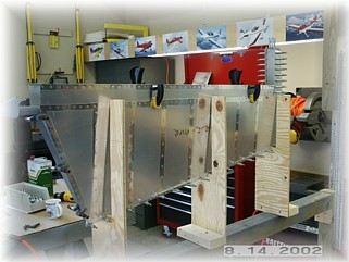
When you're done it should look something like this. Set the skeleton inside the skins and cleco it together. I set mine up in the jig and began riveting the skins starting in the center of the spar and working outward. The only problem I had was that I can't seem to find a way to set the last three rib rivets closest to the trailing edge. I chose to just use countersunk pop rivets and fill them. This is not quite as elegant as setting solid rivets, but once the whole airplane is finished and painted, it won't be noticeable.
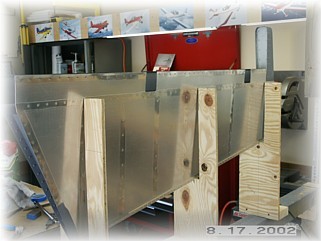
For now, the right elevator is done. All that remains is to roll the leading edge and to attach the counterweights. I will complete these steps on both elevators at the same time. Left Elevator Trim Motor Mount
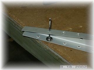
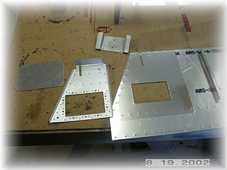
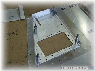
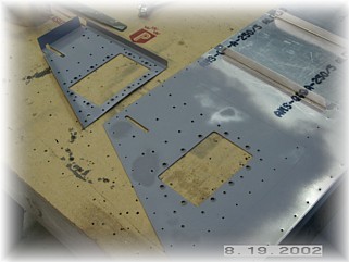
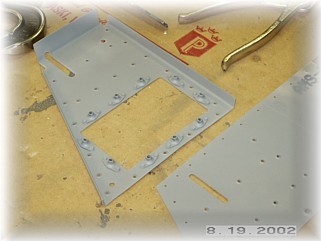
The first step in finishing up the left elevator skins for drilling and riveting is to attach the trim motor reinforcing bracket and cover. There are three parts to assemble. The opening in the skin and the bracket have been pre-cut and this is used to align the bracket in its proper position. I aligned the bracket opening with the skin opening and drilled all the mounting holes through the bracket and the skin. Be sure to NOT drill the holes that hold the nut plates around the edge of the opening. These holes do not go through the skin. Also, do not drill the two #12 holes either. These are alignment holes used to produce the part and are not used for anything. You should drill the screw holes though.
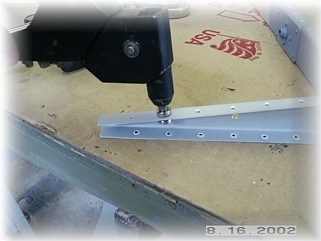
Now you can debur the holes and dimple them. Then, attach the nut plates to the reinforcing bracket. The parts are now ready to be riveted together. |
||
|
"Everyone
dies, but not everyone lives." |