|
|
| Home-->F1 Rocket Project-->Rig/Final Assembly Page 1 |
|
SITE CONTENTS
Please send your comments and suggestions to:
Copyright © 2002-2005 by
|
Links
on this page: Horizontal Stabilizer Vertical Stabilizer Elevators |
|
|
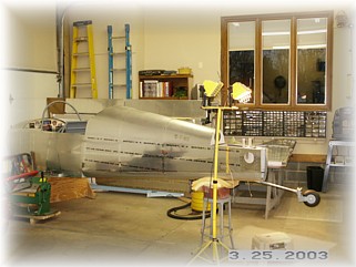
The first step in rigging the empennage is to level your fuselage both fore and aft and side to side. I secured my fuselage in the cradle and then set up my shop lights, etc for the work ahead.
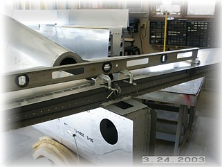
Using the spacers called out in the plans, I leveled the horizontal stabilizer side-to-side. After securing the clamps, I drilled the four attach holes. I then disassembled everything, cleaned the holes, and remounted the stab and secured it with bolts. I did all that BEFORE going on to the next step since each step builds on the success of the previous one.
I confirmed that my aft empennage deck, and as a result, my stab is level fore and aft. I then fabricated the appropriate spacers to go under the forward stab spar. My deck has a significant twist towards the left. The right spacer was according to plans. The left spacer required an additional 3/16" spacer. In the end it doesn't really mater as long as the control surfaces are in the right plane in relation to the fuselage. Before drilling these holes I also double checked to ensure that the stab was not skewed. I measured an equal distance from the aft stab spar out to the tips and made a mark. I then measured from this mark on both tips forward to the center of the aft canopy deck. I found that there are a specific series of steps to follow to get the vertical stabilizer in the right location. The plans are a little sketchy so I worked out a plan for getting each measurement correct and secure before moving on to the next. Since there are three different planes to measure, I found the following steps to be very helpful.
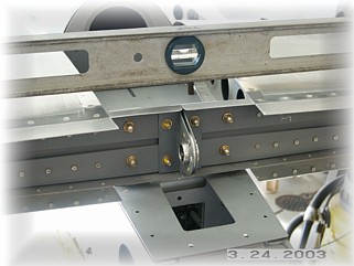
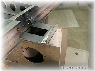
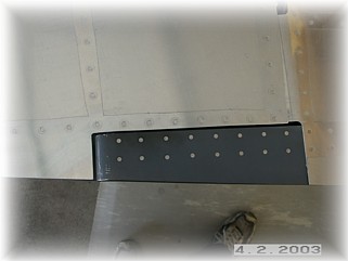
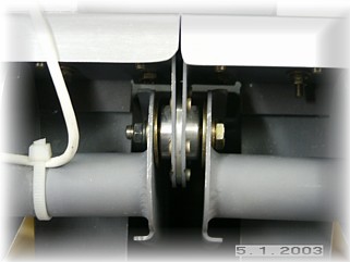
First, I followed the plans and mounted the screw in the center of the tail wheel bracket to hold the bracket in the correct beginning position. The first step is to get the vertical stab in the right vertical plane left to right. Since the spar of the vertical stab must rest against the rear fuselage bulkhead, I started there. I used my level to ensure that the fuselage bulkhead was vertically square. I then fabricated and mounted the attaching angle on the aft deck.
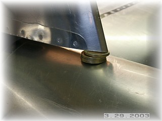
The next thing I did was drill the spar to the bottom most hole in the tail wheel mount. I drilled it to #12 and put a bolt and nut on it. This anchors the spar to the fuselage bulkhead. I then leveled a string that was pulled through the rudder hinges. This was leveled left to right. CAUTION: You cannot use this string to level fore and aft because the hinges have a 1 degree tilt to them, but they can be used side-to-side. When they were level, I drilled the two attach holes through the reinforcing angle. I then drilled the other two holes in the bottom of the spar through the tail wheel mount. I drilled them up to 'D' size, disassembled everything, cleaned up the holes, re-mounted the vertical stab, and bolted things down tight. At this point the vertical stabilizer is secured in the correct vertical side-to-side plane
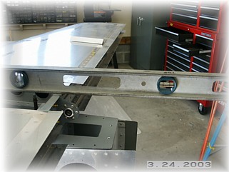
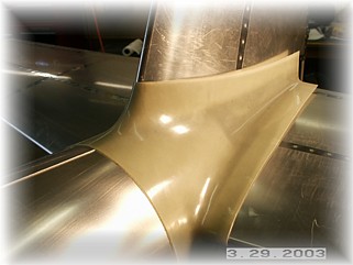
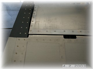
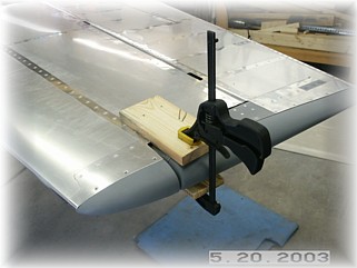
The next step is to set the twist of the vertical stabilizer. While resting on the washers, carefully clamp the front spar reinforcing plate in place. I centered mine on the horizontal stab spar and then centered the vertical stab on the plate. After a couple of adjustments, I got everything set in the "approximate" location. This confirmed for me the right location of the reinforcing plate on both spars. I trial fit the fairing just to see if my location agreed with the fairing. I then carefully removed the clamps from the horizontal stab while leaving the clamps on the vertical stab in place. I carefully removed the vertical stab from the airplane and took it over to my bench where I drilled the mounting holes for the vertical stab. After drilling them to final size, I cleaned them up and mounted them with bolts. I also predrilled the mounting holes in the reinforcing plate for the horizontal stab. Next, I remounted the vertical stabilizer again being careful to bolt it in place and to reinstall the spacer washers underneath the tip. Now's the time to get the twist accurate. I used a string down the centerline of the fuselage to check that there wasn't any twist. When I had it right, I clamped the reinforcing plate to the horizontal stab front spar and drilled three of the attach holes using the pilot holes in the plate and a long 12" drill bit. After securing them with clecos, I double checked every measurement. When I was happy, I disassembled everything and cleaned it up. Over on my bench, I drilled the plate to the horizontal spar to their final size.
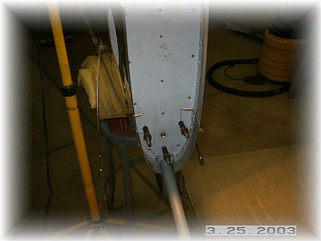
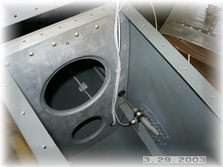
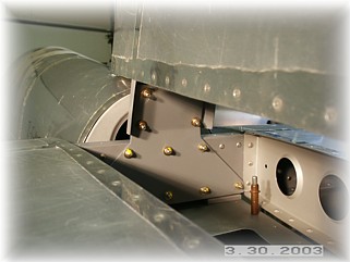
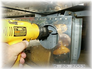
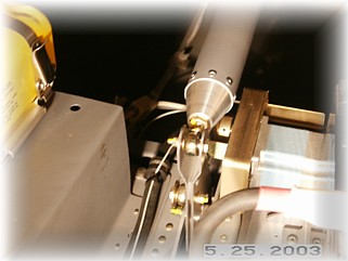
While the rear deck was off, I went ahead and finished up the wiring. I ran the trim and rear position light wires as shown in the picture. I will install a disconnect fitting on top of the rear deck later on. The wire attached to the clamp nut is the ground wire for the position light. I used my continuity tester to find a suitable place to ground the light and this worked out as good as any. I reinstalled everything for a third time and double checked all my measurements again. It all looks good. You'll notice that I haven't yet attached the rear deck plate to the fuselage. That's because I want to wait until the last moment to do this because this is a pretty cramped area to try and get your hands inside.
In laying out the elevators, I first set the bearings to the distances called out for in the instructions. Those distances didn't work for me. I then attached the elevator to the main center bearing and then measured the distance to the elevator spar. I then matched that distance on the outboard bearing. This ensured that the elevator spar would be square to the HS spar. I did this BEFORE trimming any of the skin. Now you can measure the relative distances for the elevator tips and make some initial cuts in the HS skin. Also, don't be afraid to trim the trailing edge skin of the HS to get good spacing on the elevator. The elevator must move through its entire range of motion without coming in contact with the HS. One tricky area is the outboard rounded edge of the elevator. In my case, I had to drill out the pop rivets in the elevator skin and round over the bend a little more to get the right spacing.
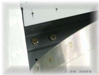
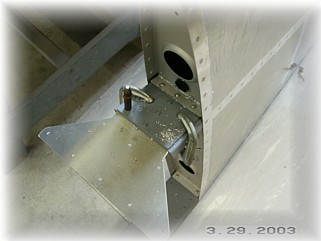
I also trimmed the rear spar of the HS to accept the elevator horns. I also had to turn around two of the mounting bolts so that the horns had enough clearance. Generally, I like to mount nuts so that they can be seen on the outside and verified during pre-flight inspection. I also mounted the horns to the bearing. I used some glue to hold both the regular washer (which you can't see) and the large washer to the horn. If you don't do this, it is very difficult to get your fingers in there to hold things in place while you try to fit the bolt. Later on, I will mount a cushion clamp to the top of the HS spar to hold the trim wire. It will go up over the spar and underneath the empennage fairing to a quick disconnect plug.
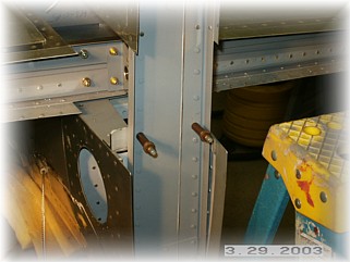
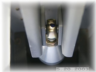
The final step in rigging the elevators is to connect the elevator horns to the fuselage bell crank via a torque tube. I first clamped the each elevator in it's neutral position. I then carefully drilled a hole through the horns. The hole should be as low and as forward as possible while still maintaining proper edge distance. If the hole is too far back, the rod end will rub on the horns when the elevators are in their full up position.
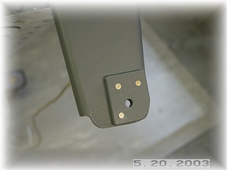
Since the space in the back of the empennage is so tight, I opted to rivet on some spacers to the elevator horns so to ease assembly. This is much easier than trying to fumble with some washers. I flush riveted the 1/8" spacers to the inside of each horn after drilling the mounting holes.
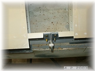
I then riveted one end of the torque tube for the bearing and mounted it to the elevator horns. I then climbed inside the fuselage to make an exact measurement on the other end of the torque tube of where it needed to be cut off. After cutting and riveting the end cap on, I final assembled everything. The important measurement here is to make sure that this bell crank is vertical when the elevators are neutral. I set this all up with about half of the bearing screwed into each end cap. I also mounted some elevator stops. For the down stop, the elevator horns hit the second-to-the-last fuselage bulkhead at 22 degrees down, which is close to the maximum deflection of 25 degrees. I chose to leave this as it was. To get the up stop at 30 degrees, I mounted a 1/4" piece of bar stock across the inside of the final fuselage bulkhead so that the elevator horns hit it. This gave me the proper deflection. Next step is to fit and mount the rudder. |
||
|
"The
higher we soar, the smaller we appear to those who cannot fly." |