|
|
| Home-->F1 Rocket Project-->Wings Page 3 |
|
SITE CONTENTS
Please send your comments and suggestions to: Copyright
© 2002-2005 by
|
Links
on this page: Attach Tie Down Ring Attach Wing Tip Wing Tip Electrical Stuff |
|
|
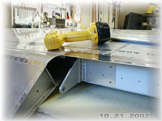
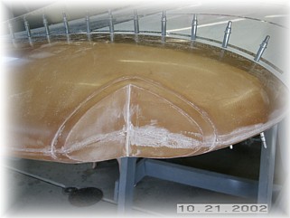
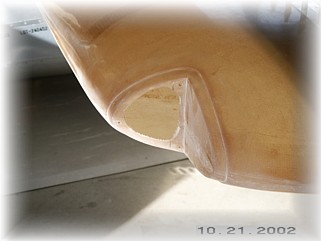
Once I had attached the flaps and flipped the wing over, I discovered a problem. There was a large bulge in the trailing edge skin where the skin goes up over the flap, between the flap and the aileron. After looking at the problem for an hour or so, I determined that the problem was the trailing edge brace behind the aileron. This skin was being held down lower than the skin needed to be and the flap was dutifully pointing this out.
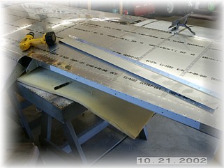
To correct the problem, I drilled out all the rivets attaching the trailing edge brace and removed the brace.
I then reattached the skin to the brace using the next size rivets. I then held the skin level with where the flap wanted the skin to go and drilled the lower attach holes through the rear spar. After cleaning up the holes, I attached the brace with pop rivets. Now the skin is flat. Whew!
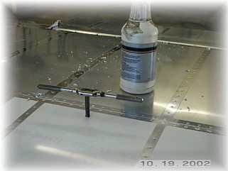
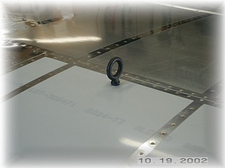
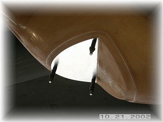
I drilled and tapped the tie down ring hole per the plans. I still haven't found a way to drill just the skin, and not the attachment, to a larger size so for now the skin hole is the same size as the screw hole. The next step is to attach the wing tip. You have several options here in terms of the attachment. You can make it permanent with pop rivets or removable by using screws. For me, removable tips are less work and provide me with more flexibility. I think they look nicer too. Also, since I plan to install my NAV antenna in the tip, I need access to the tip.
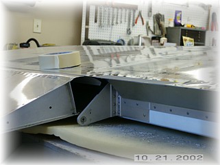
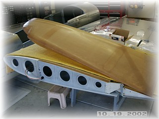
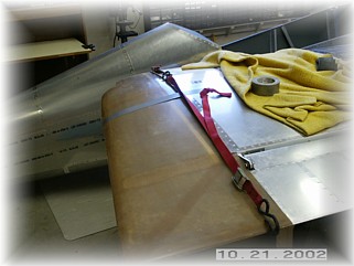
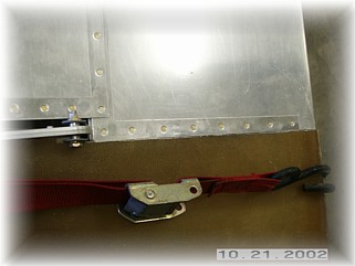
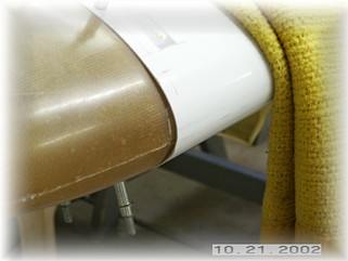
First thing that I did was trim the inboard edge of the tip a little at a time until I got the flange of the tip to fit all the way underneath the skin. I was careful to trim just a little and then trial fit the tip. I did these about 5-6 times until I had it fitting the way I wanted. You have to go slow here because if you take too much off of the tip, you can't put it back on. When I had it fitting on the skin flange, I attached a couple of straps and used them to pull the tip up into the wing until the trailing edge was even with the aileron.
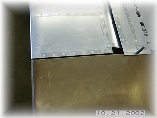
You can see in the picture that I waited until I drilled and attached the tip to the skin with clecos before making my final trim cuts next to the aileron. The most important thing to get right is the alignment of the trailing edge with the aileron/flap trailing edge. On my tip, that meant that I had a gap at the tip. That's okay because I will fix this when I finish the tip. This is pretty much standard procedure when fitting fiberglass parts. The fit on Van's parts isn't much better.
With the tips drilled to the skin, I went ahead and made my final cuts on the inside edge to the proper clearance. If you can get a straight cut here and the trailing edges to line up, you can declare victory; anything else can be repaired with sufficient quantities of body filler. I went to install the aluminum rib in the trailing edge of the tip and I found that I didn't have the parts. Apparently they were not put in the parts box when it was sent to me. So, I plan to fiberglass a rib inside the tip down its entire length to strengthen the tip and help it hold its shape. Since I may also need to do some minor fiberglassing around the light fixture area too, I will move forward on the electrical install in the tips and come back to finishing up the tip attachment stuff afterwards. In my tips, I will be installing the VonDane RV-8 landing lights and Whelen strobe units. Inside the tip on the bottom surface, I will install a Bob Archer NAV antenna. I have this part on order but haven't received it yet.
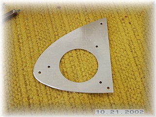
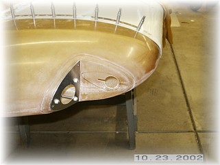
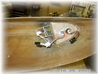
First thing I did was to use my die grinder to smooth out the mounting surfaces. I cut and fit a mounting plate for the landing light from the material provided in the landing light kit.
Leaving enough room for nut plates, I cut the tip open behind the plate as shown. I also used the template provided in the landing light instruction to cut the light hole and the light assembly mounting holes. Although not required, I went ahead and dimpled the mounting holes so that I could use flush stainless screws to mount the assembly in the tip.
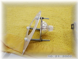
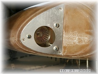
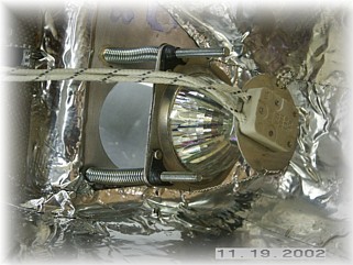
The light assembly is put together on the bench following the instructions provided in the kit. On this installation, the bulb is recessed into the tip making the final installation clean and smooth. The other nice thing is that you can remove the entire assembly from the front of the fixture. This gives you the option to permanently mount your tip because you can still service your landing light through the lens area.
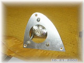
This is what the assembly looks like installed in the tip. I plan to test these lights out in my driveway at night once I finish up the electrical connections. I may need to enlarge the light hole or maybe make it oblong to provide sufficient light down and in front of the airplane. I will wait for my nighttime test before deciding what to do. It would be nice to get a lot of light out in front of the airplane to see the runway in front of you. However, unless you are installing lights a lot closer to the centerline of the airplane, I don’t think that's really possible. On my RV-6, I had the leading edge landing lights. The best you could hope for was enough light so that your peripheral vision could help you judge your height above the runway. I found that sufficient to make good night landings.
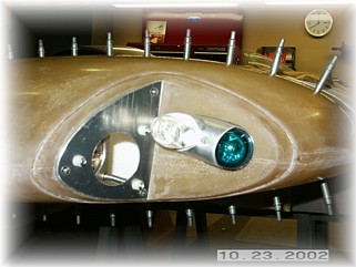
Installing the strobe/position light fixture is fairly straight forward. I used the Whelen units. I drilled the three mounting holes is conjunction with the base of the unit and then mounted nut plates behind it.
I tried to give the landing light as much room as I could along the bottom of the tip.
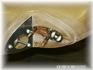
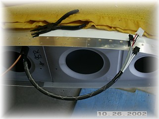
The wiring was finished up in the tip as shown above. I installed some wire loom courtesy of United Airlines and places a piece of heat shrink around each end to hold it in place. I crimped and installed Mate-N-Loc connectors on both the wires and the fixtures. You'll notice that two of the plugs are the same size, that is two wire plugs. To make sure that I don't cross these up when I plug them together, I installed male plugs on one, and female plugs on the other. That way, the wire connectors will only go together one way, and that's the correct way.
Since the halogen bulb used in the landing light projects its heat to the rear, I decided to protect the inside of the tip with some firewall foil that I got from Van's. I also drilled the lens assembly so that I could safety wire the electrical clip tot he bulb. |
||
|
"Dost thou love life? Then do not squander time, for that's the
stuff life is made of." |