|
|
| Home-->F1 Rocket Project-->Fuselage Page 2 |
|
SITE CONTENTS
Please send your comments and suggestions to: Copyright
© 2008 by
|
Links
on this page: Battery Cover Elevator Autopilot Servo Battery Tray Rudder Cables Static Air Ports |
|
|
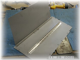
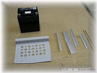
Battery Cover
I added the stiffeners to the battery cover per the plans. I also drilled slots in two places along the edge for mounting to the longeron. I also installed four countersunk screws between this panel and the rear baggage panel. Before installing the forward baggage floor/side panel, there is a bunch of work to finish up first. The forward baggage/floor panel is supposed to be installed using pop rivets. However, I think this area is an excellent place to install some electrical stuff like the strobe power unit, trim servo speed controller, along with the battery and ELT. So I plan to install this panel with screws. For now, I'll skip ahead and begin installing some of the systems that go behind and underneath the battery cover and the forward baggage/floor panel.
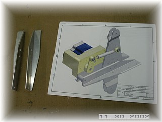
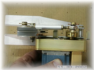
I am going to use a TruTrak two-axis autopilot. The servos come with an install kit for the F1 Rocket, which is really the elevator package for the RV-8 and the roll package for the RV-4. The first step is to remove the current elevator bell crank that is underneath the battery cover. I drilled out the rivets to remove the two angles and the bell crank assembly.
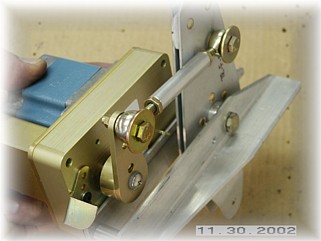
Using my own hardware, I assembled the servo and the bell crank assembly on my bench. Extra care was taken to ensure that the assembly worked smoothly. The plans were very well laid out and the servo installed on the new bell crank angles just as the plans indicated. It would be nice if they provided you with the nuts, bolts, and washers but I have an amply supply of spares to choose from. I then disassembled all the parts and primed the angles in preparation for reassembly in the fuselage.
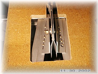
The first, and most difficult step, was to drill and rivet the angles back in the fuselage. I drilled the holes in the angle using a strap duplicator so that I could use the original mounting holes in the fuselage. After that, I riveted the angles in place. Next, I reassembled all the components and torqued things down. A final dab of torque seal finished off the job.
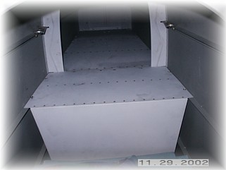
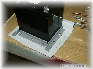
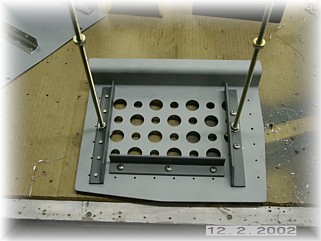
The battery tray is easy to assemble but I would recommend having your battery in-hand before assembling it. The reason is that there are many different batteries out there now, and they are all different dimensions. I picked a Panasonic battery from Digi-Key for less than $50. For me, I wanted the option to go to a different battery at a later date so I modified the installation. First, I riveted on the rear most hold down angle. This one will be fixed and is slightly more forward than shown in the plans in order to clear my autopilot servo. Next, I installed the remaining two hold down angles with screws and nut plates. That way, if I get a different battery later, I can remove the tray, unscrew the angles, and remount them without destroying the existing tray.
Also, since the Panasonic battery is not as wide, I had to leave off one of the lightening holes on the hold down bar in order to give me adequate clearance for the threaded rod hole. I still have adequate space on the hold down bar to install a larger battery. I then drilled the mounting holes and attached the tray with screws.
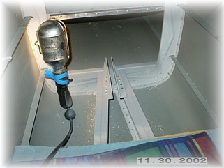
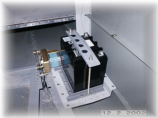
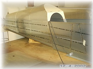
I figured that before I started bolting down the battery tray and the ELT tray, I'd better finish on some of the stuff that goes all the way back to the tail, namely the rudder cables and the static air system. So I unbolted the battery tray and went to work. Since my rudder cable fairings were installed a little higher than what the plans called for, I ignored the distance callouts in the plans. I used the front measurement of 8" and then taped a string along the outside of the fuselage to determine the right height to drill the holes. I used my Unibit to drill out the holes and install the plastic inserts.
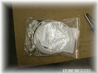
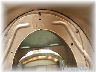
I opted for the static air kit from Van's Aircraft. I used it my RV-6, it was inexpensive, and best of all, it worked. The kit is nothing more than a couple of baffle rivets and some tubing. They also give you some fittings for your instruments. The first step is to locate a place to install the ports (rivets). I chose to install mine just aft of the rear baggage rib about in the middle of the tail cone vertically. This is about midway between the trailing edge of the flaps and the leading edge of the horizontal stabilizer. Also, I wanted it behind the bulkhead so that the tubing wouldn't be visible in the baggage area and I wouldn't be able to catch something on it and rip it off. After the rivet was installed, I used the stem to drive out the center, leaving a nice round hole to serve as the port.
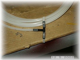
Next, I installed short pieces of the poly tubing to the plastic tee. In order to get the tubing to go on, it is necessary to hold the end of the tubing in some boiling water for a couple of seconds to soften it up. That's the real reason for doing this now rather than trying to slip these on while laying on your back contorted like pretzel. Next, the soft plastic tubing is installed on the rivets and attached to the bulkhead. At the rivets, I covered the rivet and tube with a generous amount of clear RTV and let them set up overnight. The next day, I attached the soft tubing to the bulkhead by cutting short pieces of the poly tubing and splitting them down the middle. I slipped them over the soft tubing and installed a tie wrap over each one so I wouldn't crush the softer tubing.
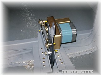
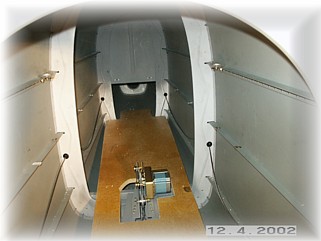
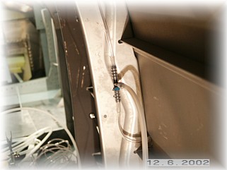
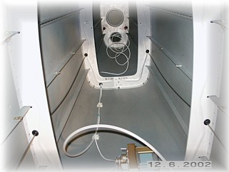
These views are from the rear empennage deck looking forward. I attached the soft tubing to the bulkhead in four places and ran it over to the tee. The tee is also attached to the bulkhead with a tie wrap. This will keep it out of the way of the rear baggage close out panel. Notice that the lowest points of the system are the ports themselves. That way any water that might make its way into the system will run out the ports and not cause a blockage. The output of the tee is now routed forward to the instruments. I will admit that what you see here took a couple of days and more swearing than I'd like to admit. At 240 pounds, I don't bend like I did when I was young and my shoulders and butt refuse to fit into these tight quarters. To have to reach behind this bulkhead to install the tubing took some real contortions. Now, where did I leave the telephone number of my chiropractor?
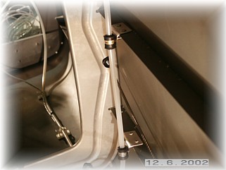
One detail to watch for is to ensure that the tube does not rub against the rudder cable. I riveted a couple of angles to the stringers and installed a nut plate for a cushion clamp. These hold the tubing out away from the cable. I routed the tubing forward toward the ELT tray. I also took this opportunity to run the wires for the elevator trim motor and rear position light as well. When everything is all buttoned up, you won't see a thing. Installing the ELT tray is next! |
||
|
"Success
is the sum of small efforts--repeated day in and day out." |