|
|
| Home-->F1 Rocket Project-->Rig/Final Assembly Page 2 |
|
SITE CONTENTS
Please send your comments and suggestions to:
Copyright © 2002-2005 by
|
Links
on this page: Rudder Empennage Wiring Rear Access Panel Empennage Fairing |
|
|
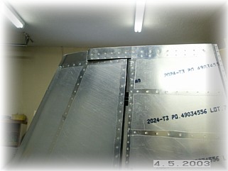
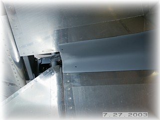
I have probably spent more time trying to rig the rudder than it took me to do both elevators. For some reason, my rudder did not fit very well. I spent a lot of time trimming the skin where the counterweight arm of the rudder swings over the VS. I had to trim so much to get it to fit, that I had to move the balance weight to the top of the rib rather than the bottom. I also had a difficult time determining the right distance of the bearings. Again, the distances in the manual were just way too close. After a bunch of trimming and fiddling, I arrived at a fit that I found acceptable. Once I mounted it back on the airframe, the bottom skin required some significant trimming. I started by leaving about a 1/2 inch overhanging the rear rib. This got me an initial fit, but the bottom of the rudder is wider than the fuselage so more trimming will be required along the bottom.
After trial fitting the bottom fairing to the rudder, I finish cut the rear fuselage skin so that the fairing would clear. Following that, I fabricated and installed the rudder stops on both sides of the fuselage.
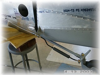
All that was left to do was install the cables and the steering arm. If you do one thing, DON'T install the springs from the kit on your rudder. I guarantee you that in the first crosswind landing that you make, you will stretch out one of the attach rings and your spring will come off the rudder horn. Dump those things in the trash and buy one of these steering arms from Terri Jantzi.
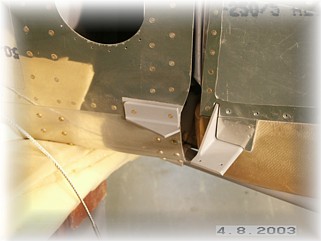
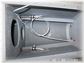
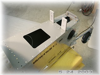
In order to finish up all the remaining details underneath the empennage deck, I completed the final wire runs. I ran the two wires to the rear position light through the bulkheads. I included a loop of wire so I had some extra if I needed it.
I chose to exit the rear bulkhead right next to the hinge bracket and just outside the vertical stabilizer spar. This allows me to remove the vertical stabilizer without messing with the wire and it also allows me to tie off the quick disconnect clip to the hinge and bearing once the rudder is installed.
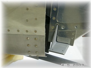
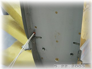
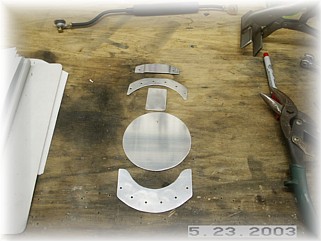
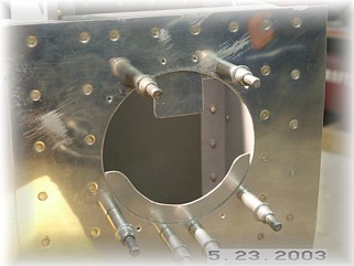
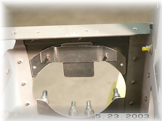
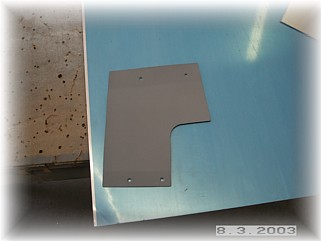
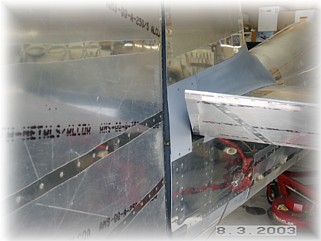
I decided to modify the attachment of the rear inspection cover. Since the area is pretty tight as it is, I decided that one mounting flange was sufficient to hold the plate in place. From .040 aluminum, I fabricated all new parts. From bottom to top, the new parts consist of a lower flange, access cover, top tab, top doubler, and top tab retainer. The only part I used from the kit was to cut the flange off of one of the parts to use it as the top doubler. The concept here is to use two #8 screws to hold the cover in place along the bottom flange. The upper edge will be held in place by a tab that slips up and rests against the longeron. The right picture shows the tab and the flange in place.
The only trick here is that the upper doubler is countersunk on both sides so that the tab can fit up inside of it. I set the top two rivets and then ground off the backside of the rivets to be flush with the doubler. Normally, I wouldn't do it this way but the holes are already drilled in the fuselage so you have to fill them with rivets.
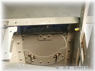
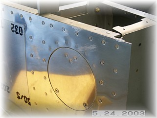
This is what it looks like all finished. The #8 screws are more than strong enough. I felt that the #10 screws supplied with the kit were too large. Since this finished up the last construction detail in the empennage, I went ahead and riveted the empennage deck in place in preparation for final assembly of all the empennage parts.
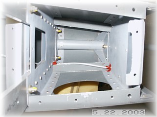
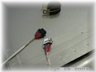
With the deck in place, I finished up the electrical connection for the elevator trim. I used a 9-pin subminiature connector and cut it down. After soldering the wires and covering them with heat shrink, I used a non-conductive glue to cover and secure them. With a simple clamp to hold the connectors in place, I covered them with a large piece of shrink wrap and finished things up. I secured the final pieces of wire with some tie wraps.
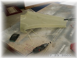
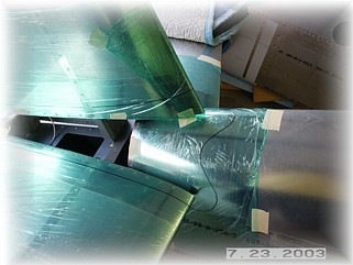
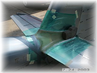
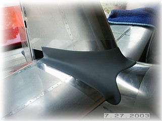
I initially trimmed the fairing along the mold lines and checked the fit with the empennage. Overall the fit was pretty good. I'm lucky in that I don't have to cut off any major pieces of the fairing. I do have some gaps along the leading edges of the horizontal stabilizer, but I can fill those with flox. I made my final cuts on the fairing. I couldn't stand to just leave the turtle deck edge straight so I cut some rounded curves in it.
I applied some cling wrap to the aluminum and taped it in place. I then marked the outline of the fairing on to the cling wrap. This will tell me where to position the fiberglass lay-ups. I first glassed two layers of cloth over on my table, then cut them to size and placed them on the empennage so they covered the outline. I then floxed up the edges of the fairing and pressed the fairing into place. I had to tape down the sides and place some bricks on the rear edge in order to get the fairing it sit in its proper location.
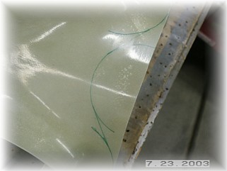
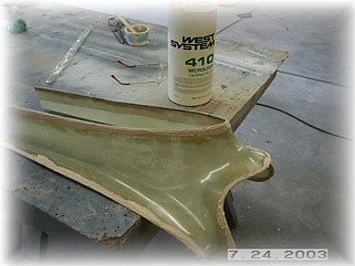
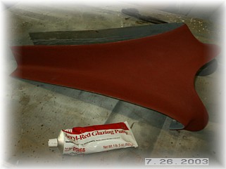
Once it dried, I carefully removed it and cut the glass to within 1/4" of the original cuts in the fairing. I then filled the edges with microballons. After sanding the edge to a nice shape, I covered the entire part with glazing putty and sanded the part smooth.
The only mounting that will be required are two screws at the rear of the fairing. I drilled out the existing rivets and replaces the rivets with nut plates. The finished part looks like this.
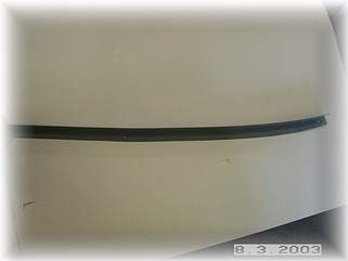
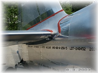
Well, I just though that I was finished with the fairing. After looking at some other airplanes at AirVenture, I decided to fabricate and install a fairing underneath the horizontal stabilizer. I took some thin aluminum sheet and bent it into an angle. I then used a stretcher to get the angle to follow the contour of the horizontal stab. I used a couple of pop rivets to mount it to the fuselage. I then decided to re-contour the fiberglass fairing to make a smoother transition between the two parts.
The final piece of the puzzle is a piece of aluminum to cover the rear opening. I fabricated the plate and used two nut plates in the vertical stabilizer. I drilled and tapped two holes in the longeron for the bottom mounting. |
||
|
|
||
|
"The
vanity of others runs counter to our taste only when it runs counter to
our vanity." |