|
|
| Home-->F1 Rocket Project-->Rig/Final Assembly Page 8 |
|
SITE CONTENTS
Please send your comments and suggestions to:
Copyright © 2002-2005 by
|
Links
on this page: Behind the Panel Music in the Cockpit |
|
|
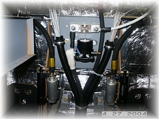
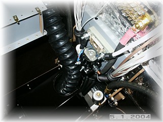
The first part of the electrical system is to bring the wires up from the center tunnel. This is where I chose to mount my starter solenoid. The device above it is a 60 AMP fuse for the primary alternator. I brought the two wire bundles up and clamped them to the bracket that I had fabricated. This now gets all the wires in behind the panel.
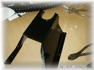
Next, I had to accommodate the fresh air line that's in the center panel. I took my cover and cut a round hole in it so that the hose would fit into it. This allowed me to bring the hose up and forward of the starter solenoid. From here, I'll route it up through the mounting panels and over to the side to the NACA vent.
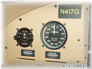
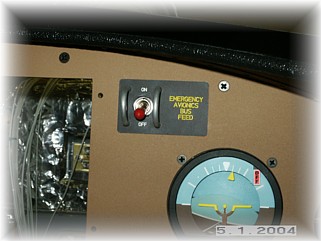
Out front, I had two little details to fix. First, I put some decals on the trim indicators and wires them up to some D-sub electrical connectors to make them removable. Since they mount from the front and not the back, I need a way to disconnect them. Second, I mounted a switch to act as my emergency avionics bus feed. I found an error in my wiring diagrams in that I had a single point of failure that could have disabled my entire panel. This switch will provide an alternate feed from the battery to my avionics bus in the event of a battery contactor failure.
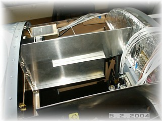
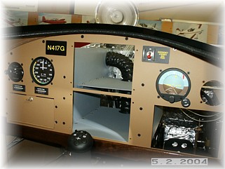
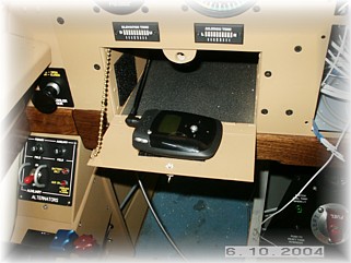
With two big square holes in the center of the panel for my two GRT EFIS units, the panel needs some additional support. It is pretty flimsy in the center. I fabricated two panels that screw to the instrument panel and are riveted to the firewall. These two panels add some rigidity and give me a place to mount a couple of shelves that will be used to mount other electrical devices.
Here are the panels with the two shelves installed. The lower shelf will hold the AHRS for the EFIS. It has to be on the centerline of the airplane and level in both pitch and roll. The upper shelf will probably hold the two alternator controllers. In the next three pictures, I'll try to show you how I laid out my wiring. I generally try to keep all the power wires away from the audio wires and the autopilot wires. That being said, it is impossible to keep them totally isolated. However, I try to avoid long runs with these groups of wires running parallel to each other. That just invites radiated noise into your audio system.
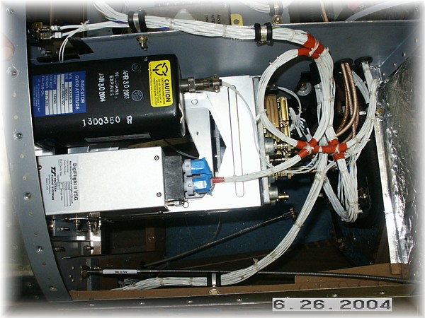
This is a picture of the right-hand side of the boot cowl area. Shown are the radio stack, autopilot, and electric gyro horizon. Most of my power wires come up the right side of the instrument panel bulkhead. That's because my switch panel is in the right armrest. There are three wire runs on this side. Most of the power wires enter a wire loom that runs to the other side of the fuselage. A second loom is up against the firewall and this contains most of my autopilot wires to the servos. The third loom runs across the top of the divider and contains the wires to the EFIS and the intercom. I had the radio stack pre-wired for my by Stark Avionics so I had a few limitations on how nice I could make all these wires look since I had to mount the pre-wired loom as it came from Stark.
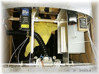
This is a picture of the left-hand side of the boot cowl area. Here I have my power buses (primary and essential), the airspeed indicator, intercom, and trim indicators. Generally, my audio wires come up the left side of the instrument panel bulkhead and from over the top of the divider panels. The power wires come in through the wire loom.
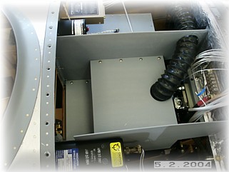
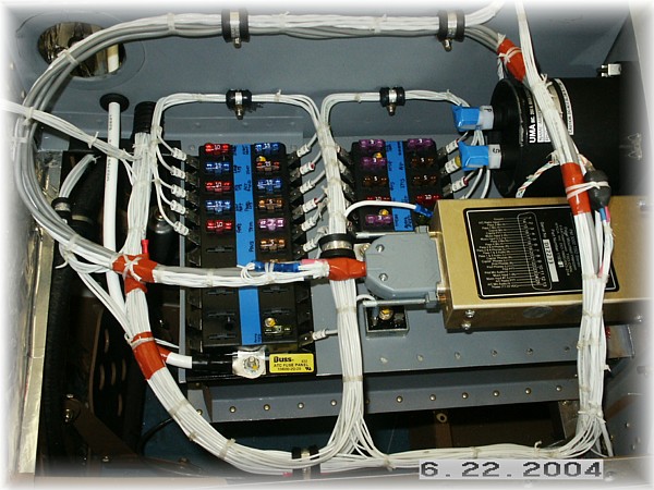
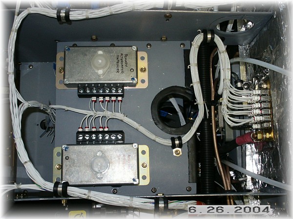
This is a picture of the center of the boot cowl area. This area actually has three shelves. The bottom shelf will contain the AHRS unit for the EFIS. The center shelf (shown) contain the alternator controllers for my two alternators. The top shelf contains the engine information computer (which drives the EFIS engine display) and the lighting heat sink. My ground bus wires also terminate in this area. You'll note that on the ground bus, I've numbered the connections. These will correspond with my wiring diagrams. This is a lesson I learned on my previous airplanes. If you are having a problem with one of your circuits, it is impossible to track down the ground point if you don't number things. Sometimes, the problem with a circuit may be an intermittent ground, as was the case on my RV-6 with the fuel gauge circuit. It took me forever to find it because I had to "ring out" all the ground connections. This time, I know exactly where each circuit terminates.
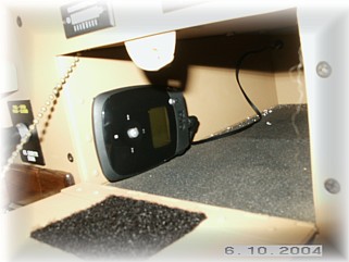
In order to get some tunes into the cockpit, I installed a portable MP/3 player and set it up so I can velcro it to the map box door. It stows on the side of the map box. I can actually play it from there if I want and keep the door closed. This little device is amazing. It weights next to nothing, doesn't skip like a CD player does, holds about 30 albums of songs in MP/3 format, and has an internal battery that lasts for about 20 hours. I thought about wiring it up so that I can charge it from the battery, but decided to keep it simple. I have the music headphone wires connected directly to my PM3000 intercom system so the CDs play in my stereo headphones. With the soft mute feature of the PM3000, the music is cut off when the intercom or radio traffic is active. The music slowly returns to normal output levels once the traffic stops. BTW, this is a RIO NITRUS and it cost about $179 at Circuit City. I've just got to shake my head when I look at the airplanes at AirVenture that have an auto CD player mounted in them. You've got to love the digital age. UPDATE: I've found that the portable MP3 player doesn't have enough power to drive the intercom system. As a result, the music volume is very low. Turns out that I need a headphone pre-amplifier. I've ordered a circuit from an electronics store and plan to construct one for my player. Stay tuned as there will be more to come. Next I'll finish up my fresh air vent. That work starts on the next page. |
||
|
|
||
|
"If you do not know where you are going, any road will take you there." - Sterling Holloway |