|
|
| Home-->F1 Rocket Project-->Rig/Final Assembly Page 3 |
|
SITE CONTENTS
Please send your comments and suggestions to:
Copyright © 2002-2005 by |
Links
on this page: Throttle Quadrant Switch Quadrant Forward Floor Panels Control Stick Fuel Valve |
|
|
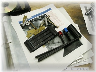
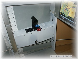
I'm using a DJM throttle quadrant that I bought from Van's. It is designed for the RV-8. I like it better than the Team Rocket quadrant because it is a little smaller, and in my opinion, in better proportion with the layout of the cockpit. However, this quadrant is designed to mount to a panel across the front. So I had to disassemble it and change the mounting around so that I could mount it to a plate on the left hand side. I then made up a mounting bracket. I sat in the airplane and fiddled with things until I had a location that I though was comfortable.
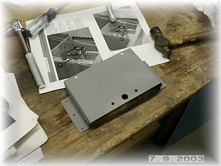
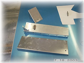
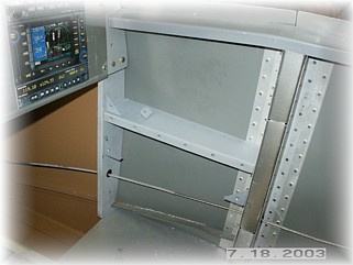
Once I had the throttle located on the side of the fuselage, I fabricated a top cover plate. Actually, I bent one so that it was the top and side all in one piece but I discovered that with this style of quadrant, I couldn't get a cover over the top of the handles. So I had to go to plan B. Since the cover must be removable, I decided to permanently mount the top cover and make the side cover removable. This made the overall installation a little more complicated than I had originally envisioned, but that happens sometimes. Once the cover was finished, I riveted it to the side skin of the fuselage.
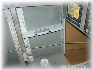
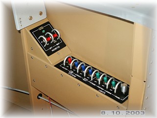
I mounted the side cover with some screws. This will allow me to gain access to the turnbuckles on the linkages. I also made a little angled cover that goes in front of the quadrant. I plan to use this space for my alternator switch and circuit breakers. I am planning a dual alternator system so I need a switch for the auxiliary alternator as well as indicators and circuit breakers for both alternators.
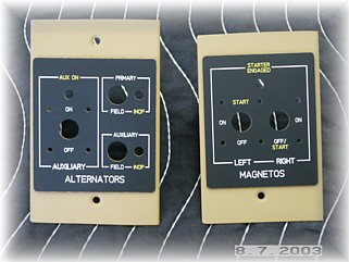
I found this cool site www.frontpanelexpress.com. I downloaded some CAD software that allowed me to build the panel just the way I like and then transmit a specification file to them that they load into their CNC machine. They then run the panel and ship it back to me. It only took about 1 week to get the panels. Above are the switch panels for both the left and right side. After mounting up the switches and stuff, painted the panels, and mounted everything. For now, that finishes the throttle quadrant. I will come back to it once I have the engine mounted so that I can mount and run the cables.
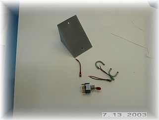
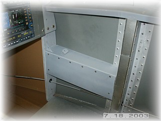
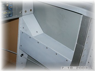
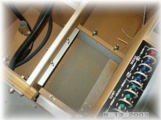
Like the left side throttle quadrant, I made up a couple of covers that I can use to mount all my electrical switches. I made the top of the panel so that it is mounted permanently. The side of the panel and the small triangular switch panel are made to come off with screws.
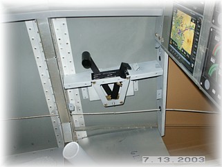
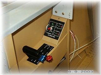
Here the panels are in their final position.
These are the switch panel covers, again from www.frontpanelexpress.com. I plan to use two switches for my magnetos/start switch. I don't really care for the key switch found in most airplanes. They are prone to electrical shorts and really don't provide much security from a theft perspective.
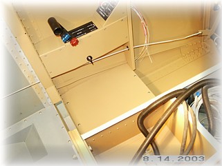
I attached the forward floor panels with screws and nut plates because I'll need access to the area underneath to put the bolts into the spar. I thought about putting a door on top of the panel but decided not to because with a slider canopy, it is difficult to reach these panels without standing on top of your head.
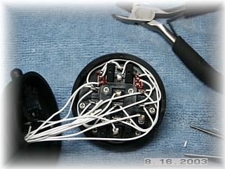
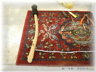
First step for me was to wire up the control stick. I'm using a Ray Allen stick with two extra switches. One of the extra switches is for the autopilot and the other is the flap switch. That meant that I had ten wires to run down the handle. I soldered things up as best I could and assembled the grip on top of the stick. I drilled a hole at the bottom and used a grommet for the wires to exit the stick.
I reassembled the stick and control yoke fitting and re-installed them back in the airplane.
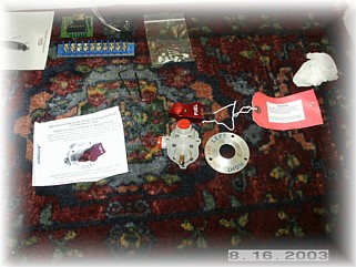
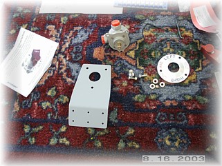
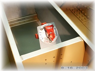
I am using a Andair fuel valve instead of the one that comes with the kit. I installed it behind the stick angling up towards the firewall. I make a bracket out of .062 aluminum plate and prepped it for installation.
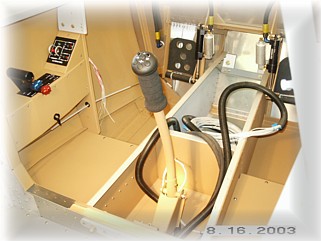
This is what the finished fuel valve looks like installed. This area will be covered with angled panels to cover the bay where all the fuel lines and pump will eventually be installed. That work starts on the next page. |
||
|
|
||
|
"I
haven't failed, I just found 100,000 ways that don't work." |